One of the less known aspect of the NanoDLP is the ability to control both SLS and Laser SLA 3d printers.
SLS is type of 3D printers create shapes by using laser to heat powders. Compare to SLA (Resin) printers quality is lower but additional support structure is not needed and high-end SLS machines use metal powder.
The most of available of these 3D printers currently are industrial and quite expensive. One of the missing puzzle piece to achieve low/mid level 3D SLS printer is software, which NanoDLP try to fill this gap.
For users whom have experience with SLA 3D printer specially NanoDLP ones. Differences to setup and use NanoDLP for SLS 3D printers could not be less. To do it just need to do following 2 steps.
- Change 3D printer mode to laser printer from the setup page.
- Enter RAMPS code for x,y axis movement on the profile page.
NanoDLP will start generating gcodes for each layer by producing customizable sequence of movement on same height and turn on / off laser.
Technology Of Mesh Repair Tool
NanoDLP Repair tool is developed using Golang language which makes it available on all platform including on your browser
Simple interface Of Mesh Repair Tool
We don’t ask you for any complex input. Just import your STL model and sit back until it’s repaired.
Features Of Mesh Repair Tool
Our tool is able to fix a wide range of faults common in the 3D industry. Let’s go over the faults our tool can address.
Self-intersection
The only way triangles are connected is by being neighbors. Mesh triangles are neighbors if they share an edge. It means they are sharing two vertices with each other. So, when a mesh triangle penetrates the other, it’s a fault.

Non-manifold edge
Neighbor triangles would share an edge. An edge consists of two vertices. However, any edge can only be shared by two triangles at most. It means, if an edge is shared by more than two triangles, it’s a fault.

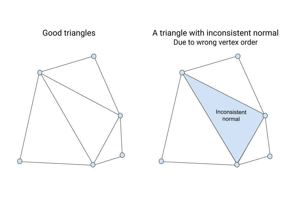
Inconsistent normal
Each triangle has a normal vector. The normal vector is perpendicular to the triangle. The neighbor triangles must have the normal in the same direction. If the normal direction is different for two neighbor triangles, it’s a fault. Normal vector inconsistency is due to triangle vertex order being messed up.
Degeneration
A triangle is degenerate if it has zero area. It can be due to three corner vertices being located on a line. It could also be due to two corner vertices being on top of each other. The latter case can happen when two corner coordinates are the same or the corner indexes are repeated.

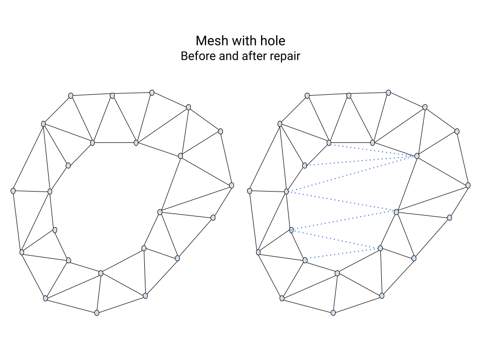
Holes
A mesh can have unwanted holes. They can actually be due to some repairs which delete bad triangles and leave holes behind. Closing holes makes sure the repair process won’t leave the mesh in a bad state.
More
There are even more features like handling out-of-bound indexes and duplicated triangles.
Conclusion
There is a chance faulty meshes are a concern for you. If so, we think our tool might help you. You can give a try on our online STL mesh repair tool. Also it is available as part of both NanoDLP and NanoSupport softwares.
Slicer converts a digital 3D model(like STL, OBJ,3MF, etc.) into specific instruction(G-code script) for printer. Without a slicer, the printer does not know what to do. As you know, 3d printing methods work by layering materials. Slicer effectively slices 3d models into flat 2d layers.
There are some offline slicer programs and software which should be downloaded and installed. In some cases, there is a web browser-based instant for slicing. Working with a Web browser-based slicer is easy and joyful. Every step, like rotation, scaling, and slice, happens in the browser.
NanoDLP slicer ported to web browsers (Using WebAssembly) and integrated into NanoDLP interface, so we provided a browser-based slicer. NanoDLP slicer is capable of processing STL and OBJ files and preparing output for SLA 3D printers, including NanoDLP controller and many others.
It includes many advanced features such as
Using the new feature you can use your computer resources to slice 3D files instead of relying on Raspberry Pi.

If your computer were produced in recent years with a mid to high-level processor, you would get much better performance on a web browser slicer than relying on Raspberry Pi.
NanoDLP-supported output formats are
- nanodlp
- nslice
- cbddlp
- ctb
- fdg
- cws
- lgs
- phz
- sl1
- pws
- pw0
- zcodex
- photon
NanoDLP documentation contains get-started guides for novice users and more advanced guides for expert users.
The new platform is relatively easy to contribute to. We hope this will create a more active community and result—also, a better understanding of both NanoDLP capabilities and the whole SLA ecosystem.
To contribute in NanoDLP documentation, you only need to click on Edit this page links below each page.

New NanoSupport has been released. It includes a new user interface and advanced auto-support algorithms.

The advantages of NanoSupport over other SLA / LCD slicers.
- NanoDLP slicer integrated into NanoSupport.
- Automatic NanoDLP detection.
- Single-click slicing and adding jobs into NanoDLP.
- High performance.
- Complete undo/redo.
software. PCB printing with a 3D printer is now easier than before with the latest version of NanoDLP. One of the best ways to make a high-resolution PCB (circuit board) is to use a technique called Photoengraving. Your SLA 3D printer could easily print PCB boards using the same method. There are different ways to do this. But what we are dealing with in this article is constructing a printed circuit using a 3D printer with NanoDLP 3D-print software. Have you heard about it? So come on till the end to understand how to do it.

Is making things in different ways interesting for you? Join us: We use a NanoDLP SLA resin 3D printer.
The new dedicated feature for PCB printing on NanoDLP SLA 3D-print software helps you to print a PCB design in PNG and JPEG formats. It automatically fits the PCB and inverts the circuit board schema.

We offer some small tricks to improve the work result and enjoy the result at the end.
1. Firstly, design the PCB in the appropriate software. The output can be a .png or .jpeg file.
2. Cut a piece of copper according to the size of the PCB and clean it with acetone.
3. Then, a small amount of SLA resin is poured on the printed surface of the printer. The copper piece is gently placed on the resin.
4. Set the printer at the start point. The printer prints the first layer of plastic onto the copper. Only you need a single layer.
5. After this step, the PCB that you placed in a plastic container filled with ferric chloride.
6. After a while, the PCB is ready.
This method looks simple and works properly. You can use this method using the latest version of Nano DLP.
Tips and tricks for PCB printing with SLA printer
1- Clean the board with Scotch Brite rather than sandpaper. The sandpaper will scratch the copper. Remove the sharp edges of the copper board with sandpaper. After that, scrub the entire surface of the copper board in smooth and uniform lines. Do not move the hand in a circle or change direction.
2- We need electrical tape to fix the copper on the plate of the printer.
3- After finishing work, remove the resin with alcohol. The resin used in this method is photosensitive. The created resin layer is an acid-resist mask.
Why use the SLA NanoDLP 3D printer?
Compared to other methods, using NanoDLP to print PCBs is faster. Printing the PCB using FDM 3D printers may take a few days.
The resolution and the quality of work using an SLA printer are very high. And the result is very accurate. So you can print complex models. Of course, due to the small bed size of the SLA printer, this method is suitable for single-layer circuits.
Using SLA NanoDLP dashboard
At your printer NanoDLP web interface, from the top menu, select plates:

Then scroll the page; you will find the PCB Print button below:

By selecting the PCB Print button, you can see the following environment.

Choose a name for your plate. Upload the printed circuit modeling file in the desired format and select the Generate button.
For more information, you can check out the online guide about PCB printing using an SLA 3D printer.
One of the basic requirements of the LCD 3D printers are to display object as sliced frames, NanoDLP supports different display engines that could be used in different situation.
NanoDLP supports many way to display images, this post try to explain how each one works, what is the best and also give a workaround for cases which one engine does not work well enough.
BCM (DispmanX)
It is a way to communicate directly with Raspberry Pi (Broadcom SOC) to display images. Performance great but only works on Raspberry Pi.
No option needed to enable it, it automatically being used if other display engine does not enabled manually.
Only reason not use it on Raspberry Pi is when NanoDLP DisplaymanX is not compatible with your display in forms of reliability issue.
Framebuffer
This is very basic form of updating the display engines. Just need to put correct path on Linux to enable it instead of BCM.
OpenGL
It is the desktop-only solution for a display engines, due to possible timing and reliability issue on desktop computers other way to control your NanoDLP suggested.
BCM (DispmanX) vs. Framebuffer vs. OpenGL
Comparison of the different engines:
| Support | BCM | Framebuffer | OpenGL |
| Raspberry Pi w. Server OS | Yes | No | No |
| Raspberry Pi w. Full OS | No | Yes (Should be Enabled) | Yes |
| Linux – Server (ARM, AMD64) | No | Yes | No |
| Linux – Desktop (ARM, AMD64) | No | Yes (Should be Enabled) | Yes |
| Windows | No | No | Yes |
| Mac | No | No (There are some workaround) | Yes |
| Performance (FPS) | Great | Good | Good |
| Compatibility | Good | Great | Good |
| Stability | Great | Great | Good |
To use NanoDLP DSI HMI, you may have limitation on which interface you can use.
For more information and up to date documentation visit our display engine documentation.
Knowing NanoDLP folder structure could be useful for many cases as listed below, consider using information on this post require basic level of Linux OS knowledge.
- Migrating your installation to new SD card.
- Recover corrupted SD card.
- Modify configuration manually.

Below you can find the basic NanoDLP folder structure after installation on Raspberry Pi and brief description of the each one.
├── config
│   ├── nanodlp.service
│   ├── nanodlp-wifi.txt
│   ├── printer.rotate
│   └── run.sh
├── db
├── distro
├── build
├── expand-fs.sh
├── LICENSE
├── NOTICE
├── printer / nanodlp
├── public
│   ├── alert.ogg
│   ├── css
│   │   ├── main.css
│   │   └── support.css
│   ├── favicon.ico
├── setup.sh
└── templates
File: printer / nanodlp
This the main NanoDLP executable to run it on linux desktop you may have file called run.sh that is easier to run NanoDLP.
One of the way that you can check if the nanodlp installed correctly or not (on Pi) is to run command below. It should see NanoDLP log indicating that the program runs correctly.
sudo ./printer
Folder: db/
This is the most important folder as it contains many json files which keep all of your NanoDLP configurations.
Folder: public/
The static files that being served for users including theme files being served from this folder, you can modify files on this folder to control look and functionality of the NanoDLP interface.
Folder: public/plates/
This folder includes plates (Jobs) that added to NanoDLP, so you can find source and sliced job files.
Folder: templates/
Include both theme HTML files and HELP files.
File: setup.sh
It is script that install NanoDLP on Raspberry Pi.
Folder: distro/
Default files for each distribution including manufacturer specific config and theme files.
File: build
File that indicate current installation manufacturer or customization name.
Folder: config/
The most of files included in this folder are configurations that related to Raspberry Pi, they are used by setup.sh.
File: expand-fs.sh
Script to expand file system on SD card. This script only useful for SBC running Linux on SD card.
For more information on NanoDLP folder structure check folder structure documentation.
NanoDLP shield is a low cost simple PCB board with stepper driver, which directly get wired to Raspberry Pi GPIO. Without any additional hardware you can control all elements of basic SLA/LCD 3D printer using this board.
There are many different types of NanoDLP shields out there. The first NanoDLP shield designed by NanoDLP team and plans shared as DIY project.
NanoDLP shields could be considered alternative of the RAMPS based control boards such as NanoDLP Official Controller Board.
Ease of Use
NanoDLP shield support fully backed into NanoDLP, with simple configuration it could be used. Wiring also simple and no complex communication going on. NanoDLP Official Controller Board also easy to use but still it is much more complicated device with more advanced use cases.
Reliability
Major problem with NanoDLP Shield is pulses being generated by NanoDLP itself and due to many technical limitation on OS and NanoDLP itself. Pulses are not perfect. So you should expect:
- It may miss steps on high speed, so it should always use with low speed. (Not much problem on SLA)
- Pulses are not in perfect form and makes stepper motor make strange sounds.
- Slicing and other heavy processing will affect movement quality and may cause missing steps.
Due to reliability issues with NanoDLP shield, majority of users using RAMPS based controller boards.
Other Differences
The functionalities of the shield are enough for basic 3D printer projects but RAMPS based boards providing so much more functionality. Shields cost also lower than RAMPS counterparts.
Cautious
Currently NanoDLP shields being produced by 3rd parties. Some may not work correctly as expected. If you are not sure about NanoDLP Shield, we strongly advise you to use RAMPS or NanoDLP Official Controller Board.
A major blind spot on resin 3D printing is lack of measurement tools for 3D manufacturers, resin producers and 3D printing enthusiasts. NanoDLP Analytic Dashboard is a new tool available to monitor both internal data and external sensors. It makes it easy to correlate data from multiple sources. It could be used together with flexible real-time code JS support to make NanoDLP decide many actions in during printing. For example pressure detection and many real-time decisions could be taken.

Internal Data Sources
Currently possible to see realtime flow of data from current sources:
- Slicer data – Solid Area, Area Count, Largest Area
- Current layer information: Cure time, Speed and etc
External Sources
It include many sensors that could be read such as:
- Moister
- Resin Level
- Driver Amper
- Light Intensity
- Pressure
- Temperature
Currently common sensors and platforms already tested
- HX711
- OpenScale
- Serial Device Reading (Comma Separated)
Features of NanoDLP Analytic Dashboard
Currently available NanoDLP features are:
- It read values both during idle and printing time. Many KPIs only available during printing.
- Both realtime monitoring and long term KPI visualization available
- Ability to reset collected data
- CSV export

How to Use NanoDLP Analytic Dashboard?
You can go to setup menu / tools page then click analytic dashboard button. Data collection will start only after visiting this page.